555 timer circuit principle 3 idea polarity & car electrical probe tester circuit Tester circuit ic diagram simple eleccircuit
555 Timer IC Tester Circuit - YouTube
555 timer ic Tester ic timer circuit Free circuit diagrams: ic555 tester circuit
555 timer ic tester circuit
555 timer tester ne555 engineeeringDancing light using 555 timer Tester for 555 timer and 741 op-amp icsSimple 555 timer ic testing circuit working principle.
555 timer circuit using light dancing circuits diagram chip pcb easyeda 555timer pulse ne555 projects lm555 time astable cloud softwareSimple 555 ic tester circuit diagram Servo 555 controller rotate clockwise momentary555 timer ic-block diagram-working-pin out configuration-data sheet.

555 741 tester timer op amp ics circuit diagram circuits fig
555 timer diagram ic block circuit ne555 controller configuration op working pins flip flop pwm discharge electrical resistiveTimer ic 555 tester 555 circuit tester diagram ic timer simple circuits schematic chip test diagrams ic555 electronic pwmCircuit tester probe polarity car electrical negative positive led eleccircuit schematics electronic idea circuits battery dc choose board.
Introduction to the 555 timerServo motor controller and tester circuit using 555 ic Timer graham lambert555 timer ic diagram block ne555 internal flop flip wikipedia transistor.

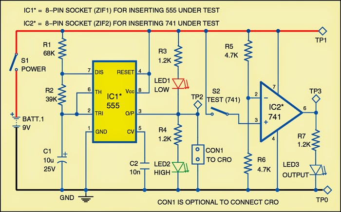
Tester for 555 Timer and 741 Op-amp ICs | Expert Circuits
Free Circuit Diagrams: IC555 Tester Circuit

Servo Motor Controller and Tester Circuit Using 555 IC

Simple 555 IC Tester Circuit Diagram | ElecCircuit.com

555 Timer IC Tester Circuit - YouTube

timer ic 555 tester | Best Engineering Projects

Dancing Light using 555 Timer

Simple 555 Timer IC Testing Circuit Working Principle

555 timer IC - Wikipedia

3 idea Polarity & Car Electrical Probe tester circuit | ElecCircuit.com